#include <commands_3dm.hpp>
|
| enum class | Feature : uint8_t {
UNUSED = 0
, GPIO = 1
, PPS = 2
, ENCODER = 3
,
TIMESTAMP = 4
, POWER = 5
} |
| |
| enum class | Behavior : uint8_t {
UNUSED = 0
, GPIO_INPUT = 1
, GPIO_OUTPUT_LOW = 2
, GPIO_OUTPUT_HIGH = 3
,
PPS_INPUT = 1
, PPS_OUTPUT = 2
, ENCODER_A = 1
, ENCODER_B = 2
,
TIMESTAMP_RISING = 1
, TIMESTAMP_FALLING = 2
, TIMESTAMP_EITHER = 3
, POWER_SHUTDOWN = 1
} |
| |
◆ Behavior
| Enumerator |
|---|
| UNUSED | Use 0 unless otherwise specified.
|
| GPIO_INPUT | Pin will be an input. This can be used to stream or poll the value and is the default setting.
|
| GPIO_OUTPUT_LOW | Pin is an output initially in the LOW state. This state will be restored during system startup if the configuration is saved.
|
| GPIO_OUTPUT_HIGH | Pin is an output initially in the HIGH state. This state will be restored during system startup if the configuration is saved.
|
| PPS_INPUT | Pin will receive the pulse-per-second signal. Only one pin can have this behavior. This will only work if the PPS Source command is configured to GPIO.
|
| PPS_OUTPUT | Pin will transmit the pulse-per-second signal from the device.
|
| ENCODER_A | Encoder "A" quadrature input. Only one pin can have this behavior. The last command to set this behavior will take precedence.
|
| ENCODER_B | Encoder "B" quadrature input. Only one pin can have this behavior. The last command to set this behavior will take precedence.
|
| TIMESTAMP_RISING | Rising edges will be timestamped.
|
| TIMESTAMP_FALLING | Falling edges will be timestamped.
|
| TIMESTAMP_EITHER | Both rising and falling edges will be timestamped.
|
| POWER_SHUTDOWN | A logic 1 applied to the pin will place the device in low-power mode. A full restart is executed after the signal is removed.
|
◆ Feature
| Enumerator |
|---|
| UNUSED | The pin is not used. It may be technically possible to read the pin state in this mode, but this is not guaranteed to be true of all devices or pins.
|
| GPIO | General purpose input or output. Use this for direct control of pin output state or to stream the state of the pin.
|
| PPS | Pulse per second input or output.
|
| ENCODER | Motor encoder/odometer input.
|
| TIMESTAMP | Precision Timestamping. Use with Event Trigger Configuration (0x0C,0x2E).
|
| POWER | Controls the device power state (e.g. enter low power mode).
|
◆ behavior
Select an appropriate value from the enumeration based on the selected feature (e.g. for PPS, select one of the values prefixed with PPS_.)
◆ DESCRIPTOR_SET
| const uint8_t mip::commands_3dm::GpioConfig::DESCRIPTOR_SET = ::mip::commands_3dm::DESCRIPTOR_SET |
|
static |
◆ feature
| Feature mip::commands_3dm::GpioConfig::feature = static_cast<Feature>(0) |
Determines how the pin will be used.
◆ FIELD_DESCRIPTOR
◆ function
◆ HAS_LOAD_FUNCTION
| const bool mip::commands_3dm::GpioConfig::HAS_LOAD_FUNCTION = true |
|
static |
◆ HAS_READ_FUNCTION
| const bool mip::commands_3dm::GpioConfig::HAS_READ_FUNCTION = true |
|
static |
◆ HAS_RESET_FUNCTION
| const bool mip::commands_3dm::GpioConfig::HAS_RESET_FUNCTION = true |
|
static |
◆ HAS_SAVE_FUNCTION
| const bool mip::commands_3dm::GpioConfig::HAS_SAVE_FUNCTION = true |
|
static |
◆ HAS_WRITE_FUNCTION
| const bool mip::commands_3dm::GpioConfig::HAS_WRITE_FUNCTION = true |
|
static |
◆ pin
| uint8_t mip::commands_3dm::GpioConfig::pin = 0 |
GPIO pin number counting from 1. For save, load, and default function selectors, this can be 0 to select all pins.
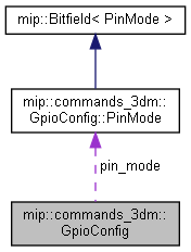
◆ pin_mode
| PinMode mip::commands_3dm::GpioConfig::pin_mode |
GPIO configuration. May be restricted depending on device, pin, feature, and behavior. See device user manual.
The documentation for this struct was generated from the following file: